Usage
Blender
Blender is a feature-rich and very powerful 3D modelling software. For this reason, however, learning how to use this software can be challenging for the beginner. The RobotDesigner plugin intends to improve the user experience as much as possible—a basic understanding of the user face and controls of Blender is mandatory. At this point, we would like to refer to a large set of tutorials provided on this matter which can be found here for instance.
The RobotDesigner
We introduce the structure of the Graphical User Interface as well as explain the workflow of creating a new robot model. If an existing model is imported the user can also start at any tab section of interest.
In the gif below you can see how to create a simple tigrillo robot with muscles from scratch using the Robot Designer. The design here includes mesh creation, kinematic and dynamics definition, visual and collision mesh attachment, muscle definition and SDF package export. The full video with audio description can be found at 1.3 Robot Designer Demo.
Creating a simple tigrillo model from scratch.
Panel overview
The various functionalities are collected in several tabs for intuitive user interaction. Creating a new robot the developer would start from the left tab to the right, or as listed below from creating a robot to exporting it.
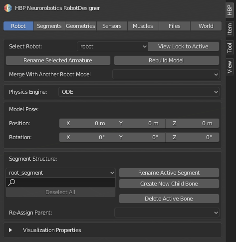
The Robot properties tab
The Robot properties tab allows us to create a new robot model or select an existing one. Hier we can also rename it or merge with another model. New segments for expanding the robot model can be created and deleted here as well. These segments are called bones in blender.
The Robot properties tab of the NRP RobotDesigner
The Segments properties tab
In the Segments properties tab we can modify the properties of the previously created segments by setting joint type, joint limits, orientation and position in relation to the parent bone.
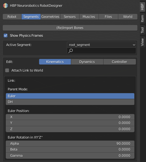
The Segments properties tab of the NRP RobotDesigner
The Geometries properties tab
The Geometries properties tab allows us to connect the kinematics model or armature created by the NRP RobotDesigner with an existing geometrical model, generate such a model or disconnect it once it has been attached. Additionally we can set basic properties as well as reduce the complexity of the geometries.
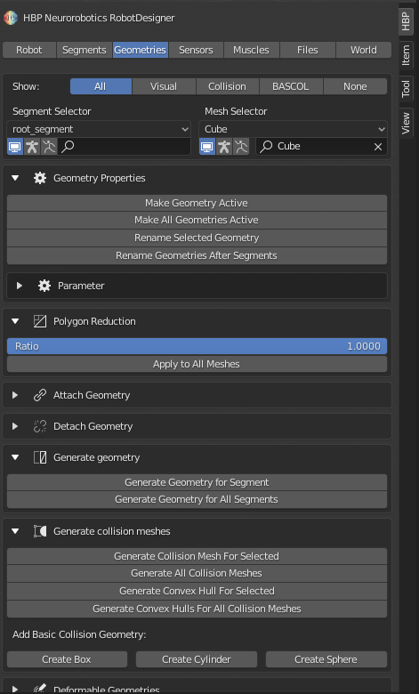
The Geometries properties tab of the NRP RobotDesigner
The Sensors properties tab
In the Sensor properties tab a camera or laser sensor can be attached, detached and its properties adjusted.
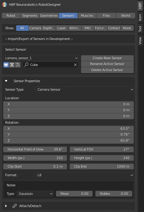
The Sensors properties tab of the NRP RobotDesigner
The Muscles properties tab
In the muscles section muscles can be defined interactively in the scene, while pathpoints and characteristics get listed in the GUI.
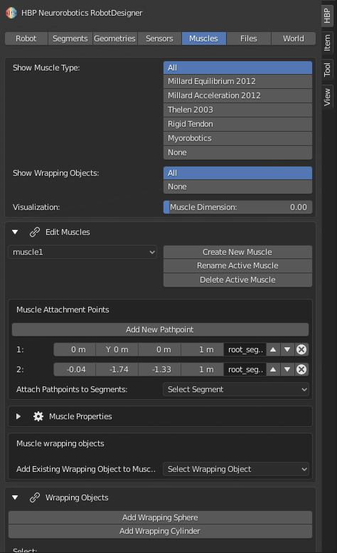
The Muscles properties tab of the NRP RobotDesigner
The Files properties tab
Here we can export the created robot model as a SDF file/package or import a robot model from an SDF file/package.
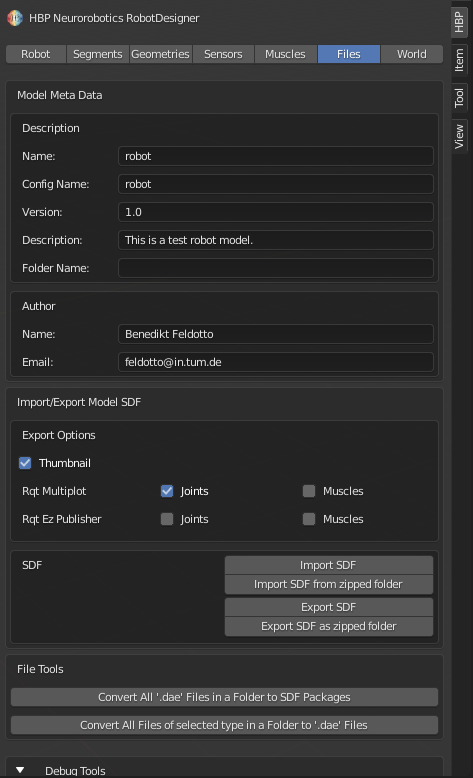
The Files properties tab of the NRP RobotDesigner
The Worlds properties tab
In the worlds tab the simulation environment can be parametrized and individual robot models can be added to the scene. The dedicated tab allows users to import existing world files and export a created environment to file.
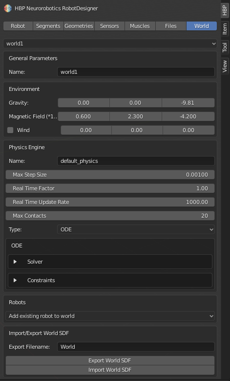
The World properties tab of the NRP RobotDesigner
Creating and maintaining robot models
The robot properties tab in the NRP RobotDesigner.
Creating a new armature.
In order to use the Robot Designer, one has first to create a blank robot model instance. Note that, in Blender, such robot models are called armatures. Through the enrichment by additional properties related to robotics they are interpreted as robot models.
In the RobotDesigner, there is a tab for modifying the robot model (see figure). In there, you can modify the name of the robot model, merge it with another model. In there, you can also modify the structure of the kinematics such as adding new / deleting segments, reparent segments (move them to a different position in the kinematics tree) and modify the names.
You can also assign different visualizations of coordinate frames (blender objects) for a more cleaned up look.
Creating robot joints/links
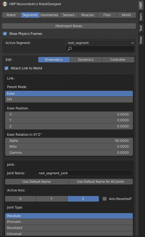
The kinematics settings in the segments properties tab of the NRP RobotDesigner.
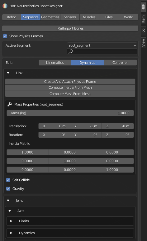
The dynamics settings in the segments properties tab of the NRP RobotDesigner.
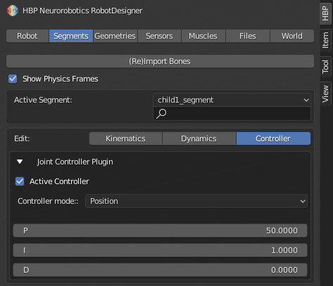
The controller settings in the segments properties tab of the NRP RobotDesigner.
Adding a new segment to an armature.
In the RobotDesigner, the smallest unit of a robot is a compound of a joint and a subsequent link called segment. That way, it becomes easy to define forked kinematics such as anthropomorphic hands. Note that, in terms of Blender, these are referred to as bones. Once a robot model has been created and selected, segments can be added to the structure to create a tree-shaped kinematics in the robots tab.
To add a new segment go to the ‘Segment structure’ field, select a parent bone from the drop-down menu and click on Create new child Bone. The new bone will be attached to the parent bone. In this field you can rename and delete segments as well.
In the segments properties tab, you can modify the kinematic and dynamic properties as well as the settings for the control software automatically assigned to the robot model when loaded into the Neurorobotics Platform. The kinematics properties basically represent transformation to the following segment (i.e., its length and orientation transformation from the parent), its rotation axis and the joint limits. Dynamics are defined via mass objects (called physics frames) that represent a mass and an inertia tensor. The controller properties include settings for maximal velocities, torques, etc. as well as the specification about how the joint of the segment is to be controlled (e.g., position or velocity controlled).
Adding and removing geometric models
The geometrical model properties tab of the NRP RobotDesigner.
Connecting the kinematics and geometrical models of a robot.
Geometric models are meshes that can be connected to a segment. In the Geometries tab. Modelling of meshes requires knowledge on how to design with Blender. The RobotDesigner unfortunately cannot support the user significantly with this task. However, existing models (e.g., those that are imported from standard CAD/Mesh file formats) can be conveniently connected to the robot model using the interface provided by the RobotDesigner in this tab.
In order to connect the kinematics model, created by the NRP RobotDesigner and the geometric model select the field Attach Geometry. First select the segment to be attached on the left and the mesh it is to be attached to on the right. After specifying the use of the geometry as visual or collision mesh, click on Assign selected geometry to active segment.
In a similar way geometries can be easily disconnected in the field Detach Geometry. First select the mesh to be disconneccted, then click on Detach selected geometry. Alternatively all meshes can be disconnected at once by selecting Detach all geometries.
Adding muscles
The video below shows the process of adding muscles with multiple pathpoints to the model by directly selecting pathpoint in the 3D environment. The full video with audio description can be found at 1.3 Robot Designer Demo.
Defining muscle on the mouse model.
Import and export
The file properties tab of the NRP RobotDesigner.
Importing a robot model of Schunk robot arm from a plain SDF file
In the file section additional meta data can be added to the model such as a model description and author contact information. One of the main strengths of the RobotDesigner is the possibility to import from and export to SDF files.
The SDF is one of the file formats the Neurorobotics Platform (or Gazebo/ROS in general) depends on. Visual and collision meshes, joints and link description as well as a model.config file can be imported and exported.